All of the labs in the first four modules in this course are building up to the labs I have in module 4. In this lab students use an H-Bridge for the first time. All of the modules up through lab four were designed with the Utah State Board of Education (USBE) Standards and Objectives for Robotics 1 in mind. I was asked to serve on the USBE committee for Robotics 1 and 2 for the state, and most of the objectives as well as state test questions in both came from me. They wanted more real world, industry recognized objectives, and I came to my first meeting with 4 pages of them.
Lab 4-2 H-Bridge Lab - 4 hrs
WARNING!
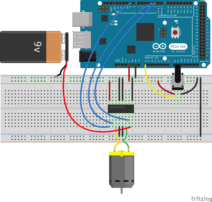
In this chapter, you use a 9V battery so that you can power motors that require more power than what the Arduino can provide. These voltages are still not high enough to pose a danger to you, but if hooked up improperly, these batteries can damage your electronics. As you make your way through the exercises in this lab, follow the diagrams and instructions carefully. Avoid short circuits (connecting power directly to ground), and while you'll be sharing the ground line between power supplies, don't try to connect two separate voltage sources to each other. For example, don't try to hook both the 9V supply and the Arduino's 5V supply into the same supply row on the breadboard.
This lab covered the following concepts:
Lab Instructions:
Lab Submission:
Video:
WARNING!
In this chapter, you use a 9V battery so that you can power motors that require more power than what the Arduino can provide. These voltages are still not high enough to pose a danger to you, but if hooked up improperly, these batteries can damage your electronics. As you make your way through the exercises in this lab, follow the diagrams and instructions carefully. Avoid short circuits (connecting power directly to ground), and while you'll be sharing the ground line between power supplies, don't try to connect two separate voltage sources to each other. For example, don't try to hook both the 9V supply and the Arduino's 5V supply into the same supply row on the breadboard.
This lab covered the following concepts:
- DC motors use electromagnetic induction to create mechanical action from changes in current.
- Motors are inductive loads that must utilize proper protection and power circuitry to interface safely with your Arduino.
- DC motor speed and direction can be controlled with PWM and an H-bridge.
Lab Instructions:
- To complete this lab, watch the videos below and setup your board and code.
Lab Submission:
- Create a video of the working lab and upload into canvas as a VIDEO SUBMISSION. You should start by talking directly into the Camera so that I can verify that it's you. Your video should take no more than 30 seconds, and you should answer all of the KEY QUESTIONS below.
- KEY QUESTIONS:
- What does and H-Bridge do?
- Why do we need to "map" the velocity variable in this code?
- This question is critical! How would you hook up another motor to this H-Bridge? See the pinout and video explanation below.
- If you need to redo an answer to key questions, you don't need to do another video. Feel free to submit your answer as a text entry in Canvas.
Video:
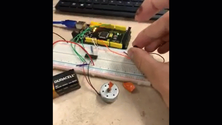
Lab Example: Motor running forward and backward
Lab Example
Code Explanation
>
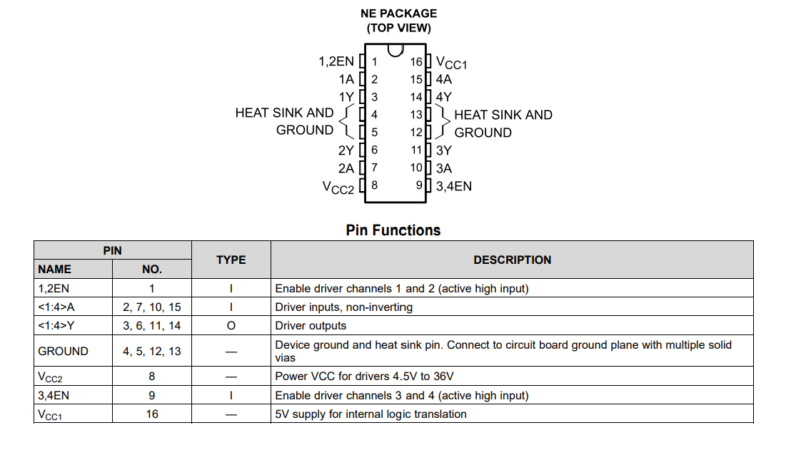
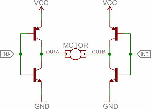
The SN754410 is an Integrated Circuit (IC), called an H-Bridge, that makes controlling motors easier. An H-Bridge allows you to control both the direction and the amount of an electrical current being supplied to a motor. You can think of it as a smart valve that allows you to change the direction of the current passing through the motor.
To switch the direction of the current, you use two pins to toggle pins on the board either HIGH or LOW. If the two direction pins are both HIGH or LOW at the same time, that causes the board to brake the motors. If one pin is HIGH and the other is LOW, the motor spins in one direction. If you flip-flop the states, the motor spins in the opposite direction. The IC is also powered separately with 5V supplied to pin 16 on the IC, and up to 36V for the motor voltage on pin 8 of the IC.
You can control up to two motors with a single IC. You can use this diagram as a reference for pin numbers in conjunction with the table below.
Board Layout:
Parts List:
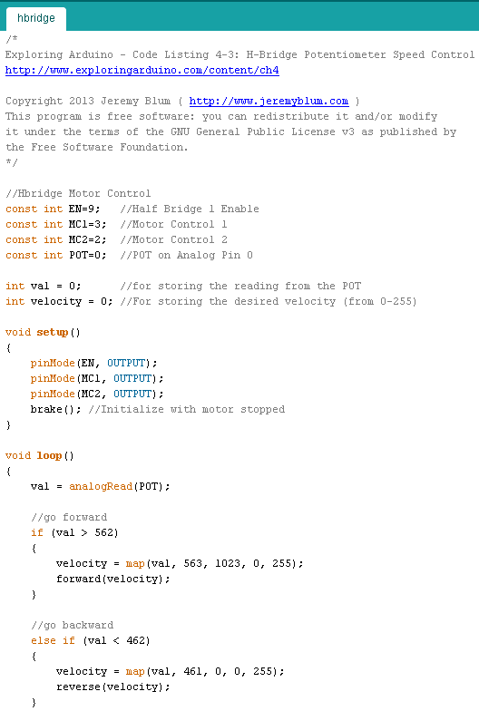
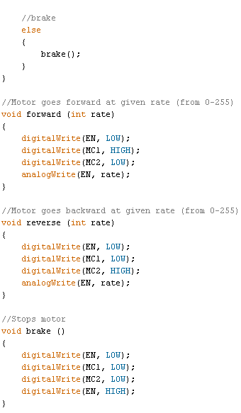
Code:
Code: